
An introduction to the construction of membranes and modules is given in the following chapter. Although this work has its emphasis on the development of new materials for membrane separation layers, the overview shows that more advanced works are necessary in order to apply these results technically.
Inhaltsverzeichnis
2.1 Membrane morphology
Membranes are principally available as porous or non-porous layers. The transport and separation mechanisms in these types of membranes are different (cp. Chapter 4.1). Porous layers are in general about several scales more permeable to gases than the dense polymer films.
The non-porous membranes can be classified in homogeneous and asymmetric. The homogeneous membranes must be as thin as possible as the highest permeability per surface in membranes is desired. This contradicts the demand for the mechanical stability. Therefore as a rule membranes are used as asymmetric membranes, in which there is a very thin and dense separation layer on a porous substructure of high permeability. If the separation layer is of the same polymer as the porous supporting layer, they are called integral asymmetric membranes. If the material of the separation layer is different to the supporting layer, they are called composite membranes.
The construction of a composite membrane is shown in Figure 2:
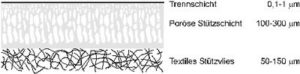
A micro porous layer is applied to a non-woven textile supporting material which protects the real supporting layer. As small defects or pores in the separation layer can lead to big losses in the selectivity of the membrane, the real separation layer is often covered with high permeable polymers (mostly polydimethylsiloxane, PDMS), which close the pores and additionally protect the thin layer mechanically [13, 14]. This invention helped the technical gas separation with membranes.
In principle there are two geometric possibilities for the design of separation gas membranes: flat membranes (cp. Figure 2) and hollow fibre membranes.
The separation layer in hollow fibre membranes is inside and/or outside of the supporting layer, which is mostly applied to porous fibres.
2.2 Membrane modules
The separation units into which the membranes are fitted, are called membrane modules. They must allow the separate conduction of the feed and permeate currents on either side of the membrane (Figure 3).
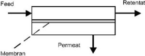
The gas mixture, which is introduced into the separation apparatus, is called the feed. This current is divided into two inside the apparatus; the one which penetrates through the membrane is called the permeate and the other stream, which leaves the unit depleted is called the retentate. There are different flow alternatives for the gas inlet in the unit. Figure 3 shows a counter current flow. In the case that the side of the permeate is continuously impinged with a flushing gas, a counter current flow as well as a co-current flow is possible for the feed inlet.
Flat membranes can be assembled as plate, bag or spiral wound modules. A plate module is constructed in a similar way to a filter press (cp. Figure 4) [15]. Each pair of membranes is separated by a spacer (feed spacer) with the separation layers stacked towards each other. Between every pair a permeate spacer is inserted as a spacer. The spacers are incorporated into frames, which simultaneously make the sealing of the module as well as the material conduction through alternating channels and drilled holes possible.
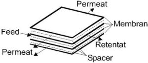
Figure 5 shows the construction of a spiral wound module [16]:

A possible configuration of a spiral wound module are two membranes with the supporting layers against each other, separated by the permeate spacer and packed into a tube provided with drilled holes. The backs of the membranes and the permeate spacer are stuck together at the edges. The complete configuration is then introduced into a pressure tube. Another module for flat membranes is a bag module [17]. Here, the membranes are welded as bags and arranged around a tube with drilled holes.
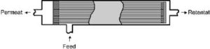
Figure 6 shows a hollow fibre module. Hollow fibre membranes are incorporated in bundles into a synthetic resin at the ends. The hollow fibres are open at the permeate side; the module shown below is a possible variant, closed at one end of the hollow fibres.
The membrane modules presented here differ basically in the obtainable packing density (membrane surface per volume of module) and the basic price, which is relatively expensive for plate modules in comparison to the spiral and hollow fibre modules (cp. Table 3).
| Type of module | Area pro volume m2·m-3 |
| Plate | 400-600 |
| Spiral | 800-1000 |
| Hollow fibre | 2000-5000 |
Consequently it is understandable why technical appliances are almost exclusively fitted with hollow fibre modules (e.g. membrane contactors [19]). However, the plate module format is chosen for laboratory tests and for the design of membranes because of the easy productivity of flat membranes without defects and the easy shape of the module (cp. Chapter 5.2).
2.2 Parameters of gas separation membranes
The most important parameters of the gas separation membranes are the permeability and the separation factors. The separation capacity and the demand of membrane for a particular separation process are a result of these properties.
2.2.1 Permeability
Stationary conditions are created through the momentum of a partial pressure difference of a particle of a flow J unit (unit: kg· m-2· s-1) through a piece of membrane with an area of A. The permeability P for the penetrating gas through a membrane is normalised as gas flow rate pro membrane surface, time and partial pressure difference (unit: Nm3(STP)·m-2·h-1·bar-1, STP: 0 °C, 101325 Pa, 22,414 l molar volume). If the membrane materials are compared, it is common to standardise the membrane surface, partial pressure difference and membrane thickness (unit: „“barrer“ 10-10 · Ncm3(STP) cm·cm-2·s-1·cmHg-1, conversion factor for the above unit: P · membrane thickness / cm · 2,0911 · 107).
Membranes with the highest permeability possible are desired as they reduce the area necessary for a separation unit, because there is a minimal membrane thickness depending on the membrane from from which the first membranes can be produced without defects.
2.2.2 Separation factor
The separation capacity of a membrane is specified using the separation factor α.
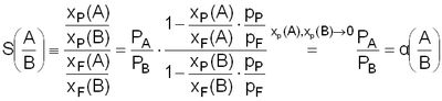
The separation factor for a couple of gases A, B is defined as the rate of the gas permeabilities P (cp. Eq. 4). The separation factor is a material constant over the whole membrane and depends on the temperature T, the feed pressure pF and the pressure difference ΔpF-P. The ideal separation factor (as specified in this study) is the permeability rate of individual gases. If the permeability measurements are carried out with gas mixtures and the individual permeabilities are determined from this, then they are called real separation factors. They are only identical to the ideal separation factors when the gases neither interact with each other nor the gases with the membrane matrix.
The separation factor α only matches with the selectivity S in the limited cases when the partial pressures of the substances A and B in the permeate side are about 0 (this value is sometimes referred to in literature as the ideal separation factor). The selectivity S is defined as the relationship between the amount of the substance in the feed xF(A,B) and the permeate xP(A,B) for the gases A (penetrate more quickly) and B (cp. Eq. 5) [20].
The determination of separation factors is mostly carried out at low pressure and usinglow-pressure differences (cp. Chapter. 6.1.1). Through this the swelling effects of the polymers, the compression (high pressure) and the anisotropic behaviour of the membranes are reduced. To compare materials which are only marginally different (e.g. modified substituents in the lateral polymer chain), it is common to extrapolate the permeabilities and selectivities to a feed pressure of 0 and to a pressure difference of 0 [cp. 21, page 24].
Separation factors are not dependent on the membrane thickness. Exceptions are membranes with very thin separation layer (< 0,1 µm) in comparison to isotropic layers (100 µm). Fromm, Pinnau and Koros found deviations of 10-20% in terms of selectivities and they traced them back, among other things, to the modified morphology of the polymers with very thin layers [22]. From Eq. 5 it is obvious that the high values of separation factors lead to the greater product purity (rate xP(A)/ xP(B)) of the more quickly penetrating substance in the permeate.
A calculation of the retentate composition is possible using a mass balance in the module (cp. Chapter 6.1.3).
If the construction of a multi-stage plant is necessary on the basis of purity requirements for the product (possible connections [23A]), a lower separation factor α of the membrane draws negative attention to itself in this case because the reduced permeate (e.g. during a serial-connection) must be compressed again and this consequently increases the specific energy consumption of the process. The separation factor α and the partial pressure difference are the most important factors for the product yield [23B]]. For example, if the retentate represents the product of the separation equipment and the permeate has to be discarded (cp. Figure 1), the lower the loss via the permeate, the bigger the separation factor α.
2.3 Energy consumption of gas separation with membranes
During processes of energy accumulation or storage (cp. Chapter 1.3.1), the specific energy consumption of the gas separation is of great importance, as through this the overall efficiency of such a process is basically determined and consequently its competitiveness in comparison to conventional methods as well.
The next model (cp. [24], page 92) can be used to calculate the minimum energy consumption for the decomposition of a gas mixture with the components A and B: there is a binary gas mixture in a flask with an amounts of the substances xA and xB, which are separated by the merging of two flasks. The flasks are composed of membranes, which are, in each case, selective for one of the components and do not oppose any resistance to the passage of the components.
The necessary work for the separation corresponds to the reversible heat of decomposition [25]. For a mol of gas the minimum isotherm decomposition work w minmin (cp. Eq. 6) is:
![]()
The minimum isothermal decomposition work is equal to the free enthalpy of mixing ΔGm. The minimum decomposition work wmin will be at its maximum in equal molar concentrations and is then at 25°C 1,7 kJ·mol -1 (0,0213 kWh·Nm-3 mixture).
However the minimal heat of decomposition is exceeded in every case as no ideal selective membranes exist and a membrane always opposes a resistance to a penetrating component. In real cases is necessary to apply the energy of compression to the feed flow for gas separation in non-porous membranes. The necessary work for the adiabatic compression is specified in Eq. 7 [25].
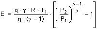
where η is the compressor efficiency, γ the ratio of the heat capacities cp/cv and q the number of moles which are compressed per second. Through the expansion of the retentate in a turbine, compression energy can be recovered.
The energy consumption of a permeate-sided vacuum pump, pressure lost in module and the resistance transport on the membrane have to be added so that the process can be considered energetically. Mulder [25] gives us the energy consumption values in Table 4 as an example for a plant which produces air with 35% oxygen (10 t·h-1).
| Process | Product purity O2/ % | Energy consumption kWh |
| Reversible isotherm | 100 | 6,0 |
| Cryogenic | 99,5 | 62,7 |
| PSA | 90 | 77,2 |
| Membranes | 35 | 50,9 |
The above values show that the effective energy consumption in this case, lies at the 8,5-fold of the theoretical minimum value.
The following can be calculated for a hydrogen storage system based on formic acid as follows (cp. Figure 1): the combustion enthalpy of a standard cubic meter of an equimolar CO2/H2-mixture is 1,529 kWh. According to Eq. 6, the minimal heat of decomposition is 0,0213 kWh·Nm-3, which corresponds to 0,0174 kWh pro kWh electric power (η = 80%, fuel cell).
Using the values in Table 4, approximately 14% of the generated electrical energy is necessary for the separation of CO2 at 25 °C.
During a mobile application of those systems, the CO2 cannot be temporally stored and must be released into the environment. In order to carry out a CO2 neutral process (cp. Chapter 1.2), CO2 must be extracted for the formic acid production, what involves a loss in efficiency in the waste gas flow (e.g. coal-fired power station, see below). If it is assumed that an average amount of CO2 is in the 13% waste gas [26], then the heat of decomposition can be calculated at 25°C using Eq. 6 (combustion enthalpy of coal 33 MJ·kg -1, η = 45%, 0,88 kg CO2 pro kWh electrical power). It amounts to 957 kJ·mol-1 CO2, what corresponds to 0,0053 kWh of decomposition heat (200°C 0,0084 kWh) pro kWh of electrical power. If real and minimal heats of decomposition are compared (Table 4), it is then expected that approximately 4% of the electrical energy generated in the power station (at 200 °C, waste gas temperature: 7%) is necessary for the separation of CO2 (PSA: 10-20% [27]).